Safety: This is not a manual for an amateur
The greatest risks on the PV side are DC electric arc, incorrect polarization, too high string voltage at low temperature, poorly selected DC devices, lack of overvoltage protection, wrong cable route and incorrect passage of wires through the roof.
General diagram of a PV installation on the roof
The diagram below shows the typical order of elements. The actual design depends on the inverter, number of MPPTs, number of strings, presence of energy storage, lightning protection system and operator requirements.
3 visual schemes: MC4 string, parallel strings and hybrid system
To make the diagram understandable, it has been divided into four separate drawings. First, a single MC4 string is shown, then parallel string connection, and finally the full system with a hybrid inverter.
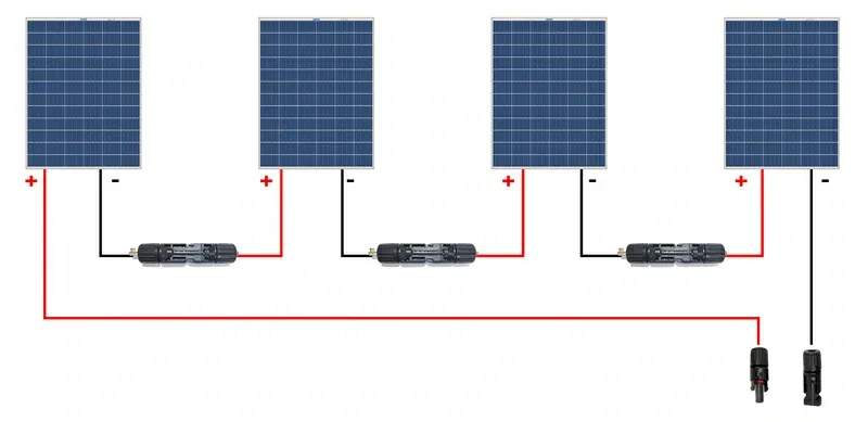
+ module → - next module. The two extreme ends of the string go to the MPPT input of the inverter.
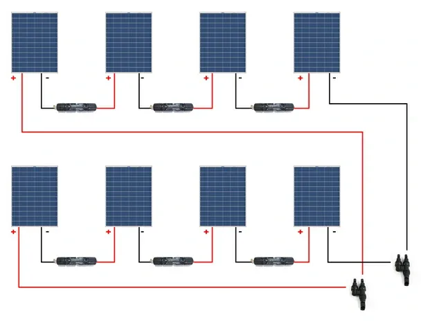
+ z + and - z -.
This connection increases the current.
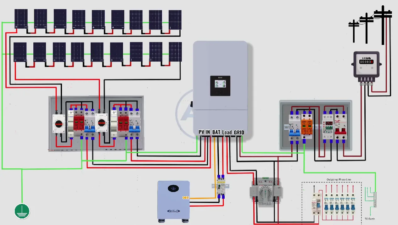
PV modules → MC4 string → parallel strings → hybrid inverter → GRID/LOAD/BATTERY.
Explanation of terms from the hybrid schema
The following concepts apply only to the tổng thể hybrid scheme. Thanks to this, the reader understands what do the inverter ports and main blocks of the system mean without going into details tủ DC.
| Term in the diagram | Meaning | What to watch out for? |
|---|---|---|
| PV / PV IN / DC1 / DC2 | Inputs of photovoltaic panels to the inverter. They usually correspond to MPPT inputs. | The strings must match the voltage and maximum current range of the MPPT input. |
| MPPT | A system in the inverter that optimizes the operation of PV panels and searches for the point of maximum power. | Different roof surfaces, different angles or different shading are usually better connected to separate MPPTs. |
| BAT / BATTERY | Battery or energy storage port. | You need to check the battery voltage, BMS type, CAN/RS485 communication and the inverter compatibility list. |
| GRID | Connection of the inverter to the building/operator's power grid. | Requires compliance with AC protection, meter, OSD conditions and energy export configuration. |
| LOAD | Output to reserve circuits, i.e. backup/emergency circuits. | It does not automatically power the entire house. Selected priority circuits are usually connected. |
| GEN | Generator/chiller input if the inverter supports this mode. | Requires configuration in accordance with the inverter manual. Not every hybrid inverter has the GEN function active. |
| Smart meter / energy meter | A meter that measures the energy flow between the house, the inverter and the grid. | It is needed for export control, auto consumption and the proper operation of many hybrid systems. |
| AC protection | Protection on the AC side: miniature circuit breakers, RCD/RCBO, SPD AC and disconnectors. | They are selected according to the inverter power, cable cross-sections, network layout and manufacturer's instructions. |
| PE/grounding | Protective conductor and connection to earth. | It is needed for protection against electric shock and proper operation of surge arresters. |
GRID connects the inverter to the grid,
and the port LOAD is used for backup circuits. These are not the same clamps and should not be confused.
Series and parallel connection of PV strings
These two diagrams show different functions. A single series string is used to increase the DC voltage, while parallel connection of several strings is used to increase the current at a similar operating voltage.
| Connection type | How does it connect? | What's growing? | What needs to be checked? |
|---|---|---|---|
| Privates | + module → - next module |
String tension | Inverter maximum DC voltage, MPPT range, Voc voltage at low temperature. |
| In parallel | + stringu → + stringu and - stringu → - stringu |
Current of the entire system | Maximum MPPT current, wire cross-section, connectors, combiner box and gPV fuses. |
Installation of PV panels on the roof – what needs to be designed?
Mechanical installation is as important as electrical installation. A poorly selected design may cause leaks, module stress, operation in the wind and service problems.
It is mounted differently on ceramic roof tiles, trapezoidal sheets, metal roofing tiles, felt, membranes and flat roofs.
The structure must be adapted to the wind/snow zone, roof angle, building height and hook/rail arrangement.
The panel needs cooling from below. Too little clearance increases cell temperature and reduces production.
You need to leave space for access, roof edges, chimneys, roof windows, lightning protection system and cable passages.
Roof planning sequence
- Checking the load-bearing capacity of the roof and covering.
- Determining the slope: direction, angle, shading, obstacles.
- Drawing the modules while maintaining the edge zones and service accesses.
- Selection of mounting structure for covering and loads.
- Establishing DC cable routes to the inverter or DC box.
- Checking for collisions with the lightning protection system and ventilation elements.
How are PV panels connected into strings?
String PV is a chain of modules connected in series. In a series connection, the module voltages add up and the string current is similar to the current of a single module. The string must match the MPPT range and the maximum DC voltage of the inverter.
10 modules of 40 V Vmpp give approximately 400 V Vmpp string.
Two identical parallel strings give approximately 2× the current of one string.
Different roof directions are usually better connected to separate MPPTs.
Patterns to check a string
The designer checks at least three things: maximum voltage in frost, operating voltage in heat and input current relative to the inverter.
Voc_string_cold = number_of_modules × Voc_of_module × temperature_correction_for_low_temperature Vmpp_string_hot = number_of_modules × Vmpp_module × temperature_correction_for_high_temperature I_string ≈ Module Imp; with parallel strings, the currents add upVoc_string_cold must not exceed the maximum DC voltage of the inverter or the rated voltage of the DC devices. This is one of the most important design mistakes when it comes to thongs.plus of one module to minus of the next module.What not to mix in one string?
- modules with different power and current-voltage parameters;
- modules facing different directions if they work on one MPPT;
- modules from different areas with strongly different shading;
- old and new modules without converting string parameters.
DC switchgear: string fuses, DC SPD and switch disconnector
The DC side of a PV installation requires devices designed for DC current and PV voltages. They must not be replaced with random AC units.
| Element | Function | What to watch out for? |
|---|---|---|
| gPV string fuse | It protects the string against reverse current from other parallel strings. | The selection depends on the Isc of the module, the number of parallel strings and the maximum module protection current from the data sheet. |
| DC fuse base | Enables installation of the gPV insert. | It must be rated for the appropriate DC PV voltage and short-circuit current. |
| DC isolating switch | Enables safe disconnection of the DC side from the inverter. | Must have DC PV category and voltage; it is not an ordinary AC switch. |
| SPD DC | Limits overvoltages on the side of panels and DC cables. | The type, voltage Ucpv and connection system for the installation and LPS are selected. |
| PE terminal / potential equalization | It connects the structure, frames and devices with the protective system. | Grounding conductors must have the correct cross-section and routing. |
| DC housing | Protects equipment against dust, moisture and touch. | The IP rating, UV resistance and location must match the installation conditions. |
When to use string fuses?
A string fuse is needed when reverse current from other parallel strings may flow through a damaged string or when it is required by the project, standard, inverter or module data sheet. In systems with multiple parallel strings, each string is typically secured separately.
In practice, the selection of the gPV insert depends on the short-circuit current of the module Isc and the permissible maximum protection of the module from the data sheet.
Example DC box layout
AC switchboard: circuit breakers, RCD, SPD and inverter connection
On the AC side, the inverter is an energy source connected to the building's installation. The AC switchgear must provide cable protection, inverter disconnection, overvoltage protection and compliance with operator requirements.
| Element AC | Function | Design notes |
|---|---|---|
| AC circuit breaker | Protects the inverter AC cable against overload and short circuit. | It depends on the inverter power, current, cable cross-section and installation method. |
| AC service disconnect | Allows you to disconnect the inverter on the AC side. | It should be accessible and clearly marked. |
| RCD/RCBO | Residual current protection if required by inverter design and type. | The type of RCD depends on the inverter instructions and possible DC components of the leakage current. |
| SPD AC | Surge protection on the mains side. | The choice of type depends on the lightning protection system, network layout and risk assessment. |
| Meter/pre-meter protection | Settlement point and connection power limits. | Requires compliance with connection conditions and DSO documentation. |
Lightning protection, grounding and SPD surge arresters
Installing PV on the roof changes the situation of the building in terms of overvoltages and equipotential bonding. You need to check whether the building has an external LPS lightning protection system, what the separation distance is and how the DC cables are routed.
SPD DC i SPD AC
- SPD DC is mounted on the side of the PV cables, selecting the voltage
Ucpvto the maximum string tension. - SPD AC is installed on the network side of the inverter, depending on the switchgear and the building's overvoltage protection system.
- In a building with a lightning protection system or an increased risk of overvoltage, the design may require a type 1+2 SPD instead of type 2 only.
- SPD connections to PE should be as short as possible and carried out in accordance with the manufacturer's instructions.
Grounding of structures and panel frames
The mounting structure, module frames and metal elements should be equipped with equipotential bonding according to the design. It is especially important to use appropriate clamps, washers and cables intended for outdoor use.
Fire protection requirements, markings and cable routes
In Poland, PV installations with a power greater than 6.5 kW require additional fire protection procedures. The design should be agreed with a fire protection expert, and after the installation is completed, the appropriate State Fire Service authorities should be notified in accordance with current regulations.
What should be marked?
- presence of a photovoltaic installation on the building;
- DC cable routes if relevant to rescue operations;
- location of the inverter and DC/AC switchboards;
- main AC and DC disconnection points;
- installation diagram available to the user and service.
DC cable routes
DC cables should be routed to reduce the risk of mechanical damage, overheating, DC arcing and disruption to service operations. Avoid sharp edges, loose loops, water collection areas and unnecessarily long routes inside the building.
Measurements and acceptance of PV installations
After installation, the installation should undergo measurements and documentation control. This is not a formality - errors on the DC side may not be immediately visible, but increase the risk of failure or fire.
| Control | What to check? | Why? |
|---|---|---|
| Thong polarization | Correct plus/minus before connecting the inverter. | Incorrect polarity may damage the inverter or DC devices. |
| Voc of each string | Open circuit voltage comparison with design. | Detects wrong number of modules or wrong connection. |
| Thong current | Comparison of parallel/string currents. | Detects shading, connection errors or damaged modules. |
| Insulation resistance | Insulation of DC cables to ground. | Important for the safety and operation of the inverter. |
| PE continuity | Equalizing connections of structures and devices. | Required for protection against electric shock and overvoltage. |
| SPD test and markings | Status of SPD indicators, circuit description, diagrams. | Facilitates service and rescue operations. |
Technical checklist before acceptance
Technical and normative sources
When designing and accepting, use current standards, instructions from module/inverter manufacturers and the requirements of the local DSO. Standards and documents regarding PV installations, electric shock protection, overvoltage protection, DC disconnection and fire protection procedures are particularly important.
- IEC 60364-7-712 – requirements for electrical installations of PV systems.
- IEC 62548 – design requirements for PV generators/systems.
- PN-EN IEC 61643-31 – surge arresters for DC photovoltaic applications.
- PV module installation instructions and module catalog card.
- Inverter installation instructions and list of acceptable protections.
- OSD requirements and fire protection documentation. for installations above 6.5 kW.
FAQ
Does every PV string have to have a fuse?
Not always. A string fuse is needed when dangerous reverse current from other parallel strings may occur or is required by a design, standard, module card or inverter. For a single string on MPPT, a separate gPV insert is often not used, but the decision must be confirmed by the design.
Can I use a regular AC fuse on the DC side?
NO. The DC PV side requires devices designed for DC PV and the appropriate voltage. The DC arc is more difficult to extinguish than in AC circuits.
What does SPD type 1+2 in PV mean?
This is a surge arrester that combines the function of protection against surge current and overvoltage. May be required in installations with external lightning protection or where there is an increased risk of overvoltage. The selection depends on the project.
Can DC cables run through the attic?
They can if the design includes a safe route, mechanical protection, markings and fire protection requirements. Unnecessarily long DC paths inside the building should be limited.
How to choose the number of modules in a string?
You need to check the Voc voltage at the lowest temperature, the Vmpp voltage at the high temperature, the MPPT range of the inverter, the input current and the module parameters. The number of panels is not selected only by dividing the installation power by the module power.